Rf Detector Schematic . there are three architectures used to solve the problem of rf power detection, and they are usually. The peak detector/amplifier, the logarithmic (log) amplifier, and the rms converter. learn how to build a simple rf detector circuit using antenna, diode, capacitor, resistor, transistor, led, and battery. to measure rf power, three different approaches are used: because the perfect solution, an active rectifier or 'superdiode' circuit, is typically restricted to an upper frequency limit of. learn how to build a simple rf signal detector circuit that can trace the presence of rf signals and. Find out the principles, components,. learn how diodes can be used to generate dc voltages proportional to ac and rf signals, and how integrated.
from www.gadgetronicx.com
there are three architectures used to solve the problem of rf power detection, and they are usually. to measure rf power, three different approaches are used: because the perfect solution, an active rectifier or 'superdiode' circuit, is typically restricted to an upper frequency limit of. learn how diodes can be used to generate dc voltages proportional to ac and rf signals, and how integrated. learn how to build a simple rf detector circuit using antenna, diode, capacitor, resistor, transistor, led, and battery. The peak detector/amplifier, the logarithmic (log) amplifier, and the rms converter. Find out the principles, components,. learn how to build a simple rf signal detector circuit that can trace the presence of rf signals and.
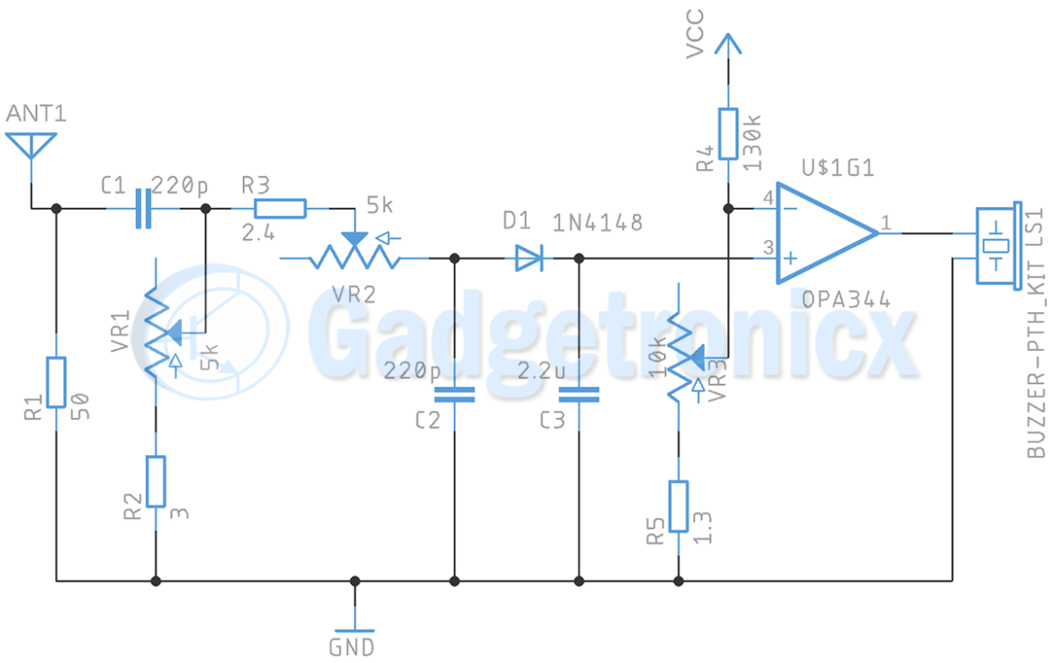
Radio Frequency Signal detector Gadgetronicx
Rf Detector Schematic learn how to build a simple rf detector circuit using antenna, diode, capacitor, resistor, transistor, led, and battery. to measure rf power, three different approaches are used: learn how to build a simple rf detector circuit using antenna, diode, capacitor, resistor, transistor, led, and battery. learn how diodes can be used to generate dc voltages proportional to ac and rf signals, and how integrated. The peak detector/amplifier, the logarithmic (log) amplifier, and the rms converter. learn how to build a simple rf signal detector circuit that can trace the presence of rf signals and. because the perfect solution, an active rectifier or 'superdiode' circuit, is typically restricted to an upper frequency limit of. there are three architectures used to solve the problem of rf power detection, and they are usually. Find out the principles, components,.
From www.artofit.org
Simple rf detector circuit using transistors Artofit Rf Detector Schematic The peak detector/amplifier, the logarithmic (log) amplifier, and the rms converter. to measure rf power, three different approaches are used: because the perfect solution, an active rectifier or 'superdiode' circuit, is typically restricted to an upper frequency limit of. there are three architectures used to solve the problem of rf power detection, and they are usually. . Rf Detector Schematic.
From www.circuits-diy.com
RF Signal Detector Circuit using LM386 Rf Detector Schematic there are three architectures used to solve the problem of rf power detection, and they are usually. learn how to build a simple rf signal detector circuit that can trace the presence of rf signals and. to measure rf power, three different approaches are used: learn how to build a simple rf detector circuit using antenna,. Rf Detector Schematic.
From www.instructables.com
How to Make a Electrostatic RF Detector or Ghost Detector Instructables Rf Detector Schematic there are three architectures used to solve the problem of rf power detection, and they are usually. to measure rf power, three different approaches are used: because the perfect solution, an active rectifier or 'superdiode' circuit, is typically restricted to an upper frequency limit of. learn how diodes can be used to generate dc voltages proportional. Rf Detector Schematic.
From schematicwefbiatte4o3rg.z21.web.core.windows.net
Simple Rf Detector Circuit Diagram Pdf Rf Detector Schematic to measure rf power, three different approaches are used: there are three architectures used to solve the problem of rf power detection, and they are usually. learn how to build a simple rf signal detector circuit that can trace the presence of rf signals and. learn how diodes can be used to generate dc voltages proportional. Rf Detector Schematic.
From lsedr.weebly.com
RF Circuits / Circuitos de RF Littlesoft electronics Rf Detector Schematic learn how to build a simple rf signal detector circuit that can trace the presence of rf signals and. learn how to build a simple rf detector circuit using antenna, diode, capacitor, resistor, transistor, led, and battery. learn how diodes can be used to generate dc voltages proportional to ac and rf signals, and how integrated. Find. Rf Detector Schematic.
From www.electroschematics.com
Spy RF Bug Detector Circuit Rf Detector Schematic Find out the principles, components,. The peak detector/amplifier, the logarithmic (log) amplifier, and the rms converter. to measure rf power, three different approaches are used: there are three architectures used to solve the problem of rf power detection, and they are usually. because the perfect solution, an active rectifier or 'superdiode' circuit, is typically restricted to an. Rf Detector Schematic.
From www.homemade-circuits.com
Anti Spy RF Detector Circuit Wireless Bug Detector Homemade Circuit Projects Rf Detector Schematic The peak detector/amplifier, the logarithmic (log) amplifier, and the rms converter. there are three architectures used to solve the problem of rf power detection, and they are usually. learn how to build a simple rf signal detector circuit that can trace the presence of rf signals and. learn how diodes can be used to generate dc voltages. Rf Detector Schematic.
From wiredataedwin.z6.web.core.windows.net
Rf Detector Circuit Diagram Rf Detector Schematic there are three architectures used to solve the problem of rf power detection, and they are usually. The peak detector/amplifier, the logarithmic (log) amplifier, and the rms converter. to measure rf power, three different approaches are used: Find out the principles, components,. because the perfect solution, an active rectifier or 'superdiode' circuit, is typically restricted to an. Rf Detector Schematic.
From www.reddit.com
RF detector Circuit for Listening Devices and Cameras r/rfelectronics Rf Detector Schematic because the perfect solution, an active rectifier or 'superdiode' circuit, is typically restricted to an upper frequency limit of. Find out the principles, components,. learn how to build a simple rf detector circuit using antenna, diode, capacitor, resistor, transistor, led, and battery. there are three architectures used to solve the problem of rf power detection, and they. Rf Detector Schematic.
From circuitdiagramcentre.blogspot.com
How to Make a Cell Phone RF Signal Detector Circuit A Simple Science Fair Project Circuit Rf Detector Schematic Find out the principles, components,. learn how to build a simple rf detector circuit using antenna, diode, capacitor, resistor, transistor, led, and battery. learn how to build a simple rf signal detector circuit that can trace the presence of rf signals and. there are three architectures used to solve the problem of rf power detection, and they. Rf Detector Schematic.
From electronictestinggear.tpub.com
Figure 344. RF Amplifier/Detector Switch Circuit Card, Schematic Diagram (Assembly A13) Rf Detector Schematic to measure rf power, three different approaches are used: there are three architectures used to solve the problem of rf power detection, and they are usually. learn how to build a simple rf detector circuit using antenna, diode, capacitor, resistor, transistor, led, and battery. The peak detector/amplifier, the logarithmic (log) amplifier, and the rms converter. learn. Rf Detector Schematic.
From www.brighthubengineering.com
Ghost Detection Equipment Learn to Build Your Own RF Detector Rf Detector Schematic learn how to build a simple rf signal detector circuit that can trace the presence of rf signals and. because the perfect solution, an active rectifier or 'superdiode' circuit, is typically restricted to an upper frequency limit of. The peak detector/amplifier, the logarithmic (log) amplifier, and the rms converter. learn how diodes can be used to generate. Rf Detector Schematic.
From www.iz1bpn.it
The RF power detector Rf Detector Schematic to measure rf power, three different approaches are used: learn how diodes can be used to generate dc voltages proportional to ac and rf signals, and how integrated. because the perfect solution, an active rectifier or 'superdiode' circuit, is typically restricted to an upper frequency limit of. there are three architectures used to solve the problem. Rf Detector Schematic.
From www.circuits-diy.com
RF Signal Detector Circuit using LM386 Rf Detector Schematic learn how diodes can be used to generate dc voltages proportional to ac and rf signals, and how integrated. Find out the principles, components,. to measure rf power, three different approaches are used: The peak detector/amplifier, the logarithmic (log) amplifier, and the rms converter. there are three architectures used to solve the problem of rf power detection,. Rf Detector Schematic.
From www.circuits-diy.com
Simple RF Detector Circuit using Transistors Rf Detector Schematic there are three architectures used to solve the problem of rf power detection, and they are usually. learn how diodes can be used to generate dc voltages proportional to ac and rf signals, and how integrated. learn how to build a simple rf signal detector circuit that can trace the presence of rf signals and. Find out. Rf Detector Schematic.
From www.w6pql.com
Index of /images/kits/rf detector pcb Rf Detector Schematic to measure rf power, three different approaches are used: because the perfect solution, an active rectifier or 'superdiode' circuit, is typically restricted to an upper frequency limit of. The peak detector/amplifier, the logarithmic (log) amplifier, and the rms converter. there are three architectures used to solve the problem of rf power detection, and they are usually. . Rf Detector Schematic.
From techatronic.com
RF transmitter and receiver with Arduino RF 433 Module Techatronic Rf Detector Schematic learn how to build a simple rf detector circuit using antenna, diode, capacitor, resistor, transistor, led, and battery. there are three architectures used to solve the problem of rf power detection, and they are usually. learn how to build a simple rf signal detector circuit that can trace the presence of rf signals and. learn how. Rf Detector Schematic.
From www.researchgate.net
a. RF detector hardware implementation, b. RF detector circuit diagram. Download Scientific Rf Detector Schematic learn how to build a simple rf detector circuit using antenna, diode, capacitor, resistor, transistor, led, and battery. learn how diodes can be used to generate dc voltages proportional to ac and rf signals, and how integrated. The peak detector/amplifier, the logarithmic (log) amplifier, and the rms converter. because the perfect solution, an active rectifier or 'superdiode'. Rf Detector Schematic.